
I use my ZA68 Keyboard the whole day, and as someone who’s studying computer engineering, knowing how a mechanical keyboard work under the hood is something I have to check. I’ll be showing you how exactly a mechanical keyboard works with the example of 9 keys macro pad, you will be able to build a strong knowledge on how mechanical keyboard works in general.
Components Overview
- Microcontroller (Arduino Pro Micro)
- Key Matrix (3×3 Grid)
- Diodes
- Key Switches
- PCB Traces and Connectors (or just wires if you want)
Electrical Pathway and Functionality
Key Matrix and PCB Layout
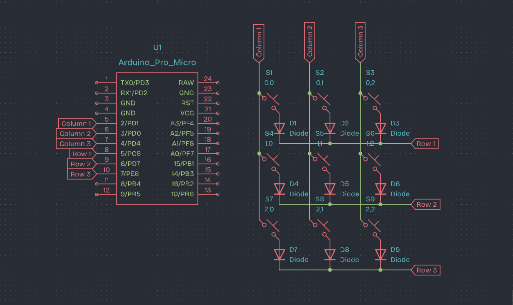
The key matrix organizes into rows and columns, with each key switch in the 3×3 matrix connecting a specific row to a specific column. The MCU systematically checks the rows and columns to detect which key is pressed.
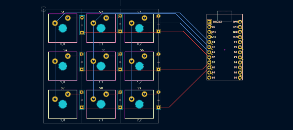
This is how the wire appears with the PCB Design.
You may have noted that we used diodes in the circuit. A diode is essentially an element that causes current to flow only in one way, allowing us to employ the anti-ghosting feature. If we did not include diodes in the circuit, the current could go in another way, where there would be no diode to stop it, resulting in “ghost” key strokes.
If you choose not to use the matrix approach, you can go for Direct Wiring, which eliminates the need for diodes and requires only key switches, a microcontroller, and cables. This is how the schematics look.
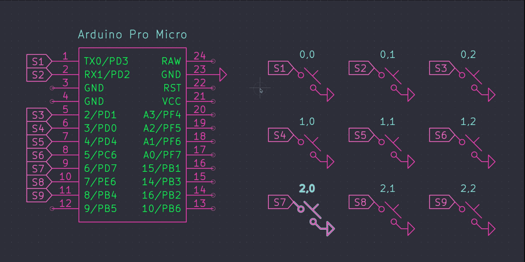
Keep in mind that you have a limited number of pins on your microcontroller, so this method only works when you have a small number of key switches. The good news is that it’s so simple that even a 12-year-old child can do it.
If you want a video explanation on how is the difference between these two methods, go and check this one from Joe Scotto, a professional on making mechanical keyboards.
Scanning Mechanism
The MCU scans the matrix by sequentially activating each row and checking which columns connect to that row via a closed switch (key press). It sets the row pins to a high state one at a time and reads the state of the column pins.
Here’s the exact code, written on an Arduino Pro Micro board:
// Define the row and column pins
const int rowPins[3] = {8, 9, 10};  // Row 1, Row 2, Row 3
const int colPins[3] = {5, 6, 7};    // Column 1, Column 2, Column 3

// 3x3 key matrix state storage
bool keyState[3][3];

void setup() {
  // Initialize row pins as outputs and set them LOW
  for (int row = 0; row < 3; row++) {
    pinMode(rowPins[row], OUTPUT);
    digitalWrite(rowPins[row], LOW);
  }

  // Initialize column pins as inputs with internal pull-up resistors
  for (int col = 0; col < 3; col++) {
    pinMode(colPins[col], INPUT_PULLUP);
  }

  // Start serial communication for debugging
  Serial.begin(9600);
}

void loop() {
  // Scan each row
  for (int row = 0; row < 3; row++) {
    // Set the current row to HIGH
    digitalWrite(rowPins[row], HIGH);

    // Read each column in the current row
    for (int col = 0; col < 3; col++) {
      // Check if the key at (row, col) is pressed
      if (digitalRead(colPins[col]) == LOW) {
        keyState[row][col] = true;
      } else {
        keyState[row][col] = false;
      }
    }

    // Set the current row back to LOW
    digitalWrite(rowPins[row], LOW);
  }

  // Print the key states for debugging
  for (int row = 0; row < 3; row++) {
    for (int col = 0; col < 3; col++) {
      Serial.print(keyState[row][col]);
      Serial.print(" ");
    }
    Serial.println();
  }
  Serial.println();

  // Small delay to avoid flooding the serial output
  delay(100);
}
Step-by-Step Scanning Process
1. Initialize Rows and Columns:
- You set all row pins to high-impedance (input mode) or pull them low.
- You set all column pins to high-impedance or enable their internal pull-ups.
2. Activate Row 1:
- Set Row 1 to a high state (logic high).
- Read the state of all column pins:
- If a column pin reads high, it means the switch connecting that column to Row 1 is pressed.
- For example, if Column 1 reads high when Row 1 is activated, it indicates that S1 (Row 1, Column 1) is pressed.
3. Deactivate Row 1:
- Set Row 1 back to low or high-impedance state.
4. Activate Row 2:
- Set Row 2 to high.
- Read the state of all column pins:
- If a column pin reads high, it means the switch connecting that column to Row 2 is pressed.
- For example, if Column 2 reads high when Row 2 is activated, it indicates that S5 (Row 2, Column 2) is pressed.
5. Deactivate Row 2:
- Set Row 2 back to low or high-impedance state.
6. Activate Row 3:
- Set Row 3 to high.
- Read the state of all column pins:
- If a column pin reads high, it means the switch connecting that column to Row 3 is pressed.
- For example, if Column 3 reads high when Row 3 is activated, it indicates that S9 (Row 3, Column 3) is pressed.
Debouncing
When you press a key, mechanical switches might send out several signals due to contact bounce. The MCU uses debouncing logic to filter out this noise, ensuring that it records only one key press despite the bouncing.
Signal Processing
When the MCU recognizes a keypress, it converts the row and column intersection into a specific keycode. Each keycode represents a specific character or function associated with that key. The MCU then transmits this keycode to the computer via USB as a HID (Human Interface Device) report.
Example Scenario
Let’s assume I press the key at Row 2, Column 3 (S6):
- The MCU activates Row 1: no column reads high.
- The MCU deactivates Row 1 and activates Row 2: Column 3 reads high.
- The MCU identifies that the key at Row 2, Column 3 is pressed (S6).
- The MCU processes this input, debounces the signal, and translates it into the corresponding keycode.
- The keycode is sent to the computer via USB.
So far, we’ve covered all of the fundamentals of creating a compact mechanical keyboard or a macro pad by focusing on the bottom layer, which is the electronics part of the process. Mechanical keyboards and membrane keyboards do not function the same way; we’ve written an article explaining the differences between them.
4 comments
You went deeper than others by explaining the hardware and software, showing true passion for understanding how things really work. This is a mindset of a True Engineer.