Have you ever wondered how your smartphone knows which way is up, or how drones manage to stay stable in flight? The secret lies in tiny sensors and some clever math. Today, we’re diving into the world of sensor accuracy and a powerful tool called the Kalman Filter.
The Challenge: Noisy Sensors
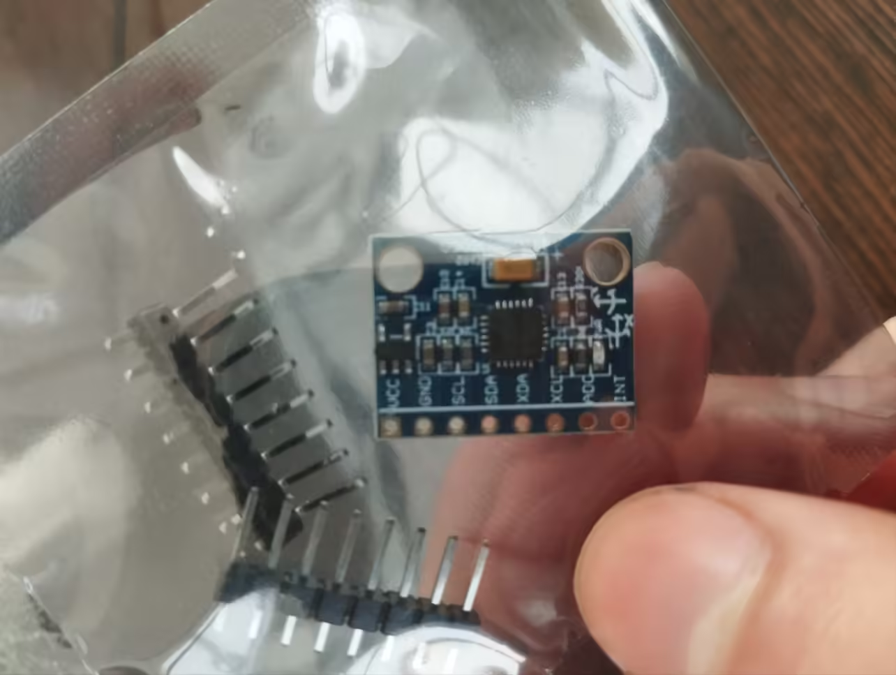
Imagine you’re building a robot that needs to balance itself. You’d use a sensor called MPU6050 to measure tilt and movement. But here’s the catch: sensors aren’t perfect. They can be a bit… noisy.
What does “noisy” mean? It’s like trying to listen to your favorite song in a crowded cafe. The music (our true sensor reading) is there, but it’s mixed with chatter and clanking dishes (the noise).
Enter the Kalman Filter: Your Digital Noise-Canceling Headphones
The Kalman Filter is like a pair of super-smart, noise-canceling headphones for your sensor data. It helps separate the “music” from the “noise”, giving you a clearer picture of what’s really happening.
How Does It Work?
Update: It combines the guess and the measurement, favoring whichever it trusts more.
Predict: The filter guesses what the next measurement should be.
Measure: It takes a real measurement from the sensor.
Compare: It checks how different the guess is from the real measurement.
Kalman Filter Implementation on Arduino Uno
Below is the code I wrote to demonstrate how the Kalman Filter works on Arduino Uno using ATMega328 microcontroller:
#include "Wire.h"
#include "MPU6050.h"

MPU6050 mpu;

// MPU6050 variables
int16_t ax, ay, az, gx, gy, gz;
const int MPU_addr = 0x68;

// Constants for Kalman filter
const double R_angle = 0.0067;  // Measurement noise covariance
const double Q_angle = 0.001;   // Process noise covariance
const double dt = 0.015;        // Time step (15ms in this configuration)

// Variables for Kalman filter
double angle = 90;
double P[2][2] = {{1, 0}, {0, 1}}; // Initial error covariance matrix

void setup() {
  Wire.begin();
  Serial.begin(9600);

  // Initialize MPU6050
  mpu.initialize();
  mpu.setFullScaleGyroRange(MPU6050_GYRO_FS_250);
  mpu.CalibrateGyro();
}

void loop() {
  // Read raw data from MPU6050
  mpu.getMotion6(&ax, &ay, &az, &gx, &gy, &gz);

  // Gyro rate calculation
  double gyroRate = gx / 131.0;

  // Kalman filter prediction step
  angle += dt * gyroRate;
  P[0][0] += dt * (dt * P[1][1] - P[0][1] - P[1][0] + Q_angle);
  P[0][1] -= dt * P[1][1];
  P[1][0] -= dt * P[1][1];
  P[1][1] += Q_angle * dt;

  // Kalman filter update step
  ax = map(ax, -18000, 18000, 0, 180);
  double y = ax;
  double S = P[0][0] + R_angle;
  double K[2];  // Kalman gain
  K[0] = P[0][0] / S;
  K[1] = P[1][0] / S;

  angle += K[0] * (y - angle);
  P[0][0] -= K[0] * P[0][0];
  P[0][1] -= K[0] * P[0][1];
  P[1][0] -= K[1] * P[0][0];
  P[1][1] -= K[1] * P[0][1];

  // Print filtered angle for debugging
  Serial.print("Filtered Angle: ");
  Serial.println(angle);

  delay(15);
}
Explanation of the Code
First, we include the necessary libraries:
Wire.hallows communication with I2C devices.MPU6050.his specifically for the MPU6050 sensor.
We then declare variables to store sensor readings (ax, ay, az, gx, gy, gz) and the I2C address of the MPU6050 sensor (MPU_addr).
Constants for the Kalman Filter are also defined:
R_angle(Measurement noise covariance) controls how much we trust the sensor measurement.Q_angle(Process noise covariance) controls how much we trust our prediction.dt(Time step) is the interval at which measurements are taken.
Setup Function
The setup() function initializes the sensor and serial communication:
Wire.begin()starts the I2C bus.Serial.begin(9600)starts the serial communication at a baud rate of 9600.mpu.initialize()initializes the MPU6050 sensor.mpu.setFullScaleGyroRange(MPU6050_GYRO_FS_250)sets the full-scale range of the gyroscope.mpu.CalibrateGyro()calibrates the gyroscope to reduce errors in measurements.
Loop Function
The loop() function runs continuously and performs the following steps:
- Read Raw Data: The function
mpu.getMotion6(&ax, &ay, &az, &gx, &gy, &gz)reads the accelerometer and gyroscope data from the MPU6050 sensor. - Gyro Rate Calculation: The gyroscope rate
gyroRateis calculated by dividing the gyroscope X-axis datagxby 131.0 (a scaling factor for the MPU6050). - Kalman Filter Prediction Step:
- Update the angle estimate based on the gyroscope data:
angle += dt * gyroRate. - Update the error covariance matrix
Pusing the process noise covarianceQ_angleand time stepdt.
- Update the angle estimate based on the gyroscope data:
- Kalman Filter Update Step:
- Map the accelerometer X-axis data
axto a range of 0 to 180 degrees. - Calculate the Kalman gain
Kwhich determines how much the prediction should be adjusted based on the measurement. - Update the angle estimate using the Kalman gain and accelerometer data:
angle += K[0] * (y - angle). - Update the error covariance matrix
Pusing the Kalman gainK.
- Map the accelerometer X-axis data
- Output Filtered Angle: Print the filtered angle to the serial monitor for debugging:
Serial.print("Filtered Angle: "); Serial.println(angle). - Delay: Wait for 15 milliseconds before the next iteration:
delay(15).
Adjusting the Kalman Filter
The R_angle and Q_angle constants can be adjusted based on your specific requirements. Higher values will make the angle variation slower, providing a smoother but less responsive angle measurement. Lower values will make the filter more responsive but less smooth.
Beyond Robots: Real-World Applications
The Kalman Filter isn’t just for robot enthusiasts. It’s used in a wide range of applications:
- Smartphones: Helping your phone’s GPS give you more accurate locations.
- Aerospace: Guiding spacecraft and satellites.
- Finance: Predicting stock prices and economic trends.
- Autonomous Vehicles: Helping self-driving cars understand their environment.
The way I used and learned this algorithm was by participating on a national competition, where we had to use MPU6050 and other components to create a self-guided robot car with an accelerometer for packet stability as well as using some technologies like RTOS. The code of my robot is on this GitHub repository.
DIY Project Ideas
Inspired to try it yourself? Here are some beginner-friendly project ideas:
- Build a Digital Spirit Level: Create a smartphone app that uses your phone’s sensors to act as a precise spirit level.
- Weather Prediction: Combine data from a home weather station with the Kalman Filter to make local weather forecasts.
- Fitness Tracker: Improve the step-counting accuracy of a simple pedometer using these techniques.
A cool documentation I’ve read about how Kalman Filter actually works is this one from Bzarg, it contains detailed explanation with pictures, feel free checking out too.
Other resources like this tutorial from MIT and this documentation from Harvard are good as well to have a comprehensive knowledge about Kalman Filter.
By implementing these techniques, you can enhance the accuracy and reliability of your sensor data, leading to better performance in your projects.
2 comments
this is very helpful, thank you so much!